Beam Failure Detection and Recovery Procedure in 5G NR
Beam Failure Detection and Recovery Procedure in 5G NR
Beam Failure detection and recovery is a very important procedure in 5G NR. I will try to explain the details in this post with as many details as possible.
What is Beam Failure in 5G NR?
In higher-frequency beam-based communications (like mmWave in Frequency Range 2 or FR2), the radio link between the User Equipment (UE) and the gNB (base station) is susceptible to sudden blockage and degradation.
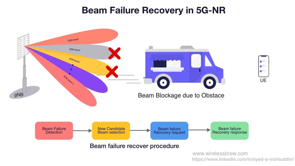
Imagine a situation where a user is sitting in a corner coffee shop streaming a movie. If a large truck stops outside the coffee shop, it can physically block the transmission path between the UE and the gNB. If the UE is unable to perform a standard beam switch fast enough, the connection drops.
To prevent this, the UE must have a mechanism to rapidly detect such sudden changes in the communication link and immediately recover from it. This is exactly what the Beam Failure Recovery (BFR) procedure in 5G NR accomplishes.
Why use Beam Failure Detection instead of Radio Link Failure (RLF)?
While 5G already has a Radio Link Failure (RLF) detection procedure, RLF operates at the upper RRC (Radio Resource Control) layer, making it relatively slow. In contrast, Beam Failure Detection and Recovery is a much faster L1/L2 (Physical and MAC layer) procedure that occurs transparently to the RRC layer.
The 4 Steps of Beam Failure Recovery
BFR is a combined PHY and MAC procedure that requires no higher-layer signaling. At a high level, the beam failure recovery procedure consists of the following four main steps:
- Beam Failure Detection (BFD)
- Best Beam Selection (Choosing a new SSB or CSI-RS)
- Beam Failure Recovery Request
- Beam Failure Recovery Response
Detailed Step-by-Step Flow for Beam Failure Detection and Recovery Procedure
The Beam Failure Detection and Recovery procedure is a critical aspect of ensuring reliable connectivity in 5G networks. Below is the step-by-step explanation of how the procedure works, following the prompt you’ve provided.
1. Variables Initialization
- BFI_COUNTER: A counter that tracks the number of beam failure instances. It is initialized to 0.
2. Check for Beam Failure Instance Indication
The MAC layer receives a beam failure instance indication from the lower layers. Action: If a beam failure instance indication is received:
- Start or Restart the beamFailureDetectionTimer: This timer tracks how long the MAC layer should wait before deciding that beam failure detection has failed.
- Increment BFI_COUNTER: The counter is increased by 1 every time a beam failure instance is indicated.
- Check BFI_COUNTER: If the counter reaches a value greater than or equal to
beamFailureInstanceMaxCount(a predefined threshold):
3. Beam Failure Recovery Check
Once the BFI_COUNTER exceeds or equals the beamFailureInstanceMaxCount, it indicates that multiple beam failures have been detected, and recovery action must be taken. Action:
Check whether beamFailureRecoveryConfig is configured for the active uplink bandwidth part (UL BWP):
- If
beamFailureRecoveryConfigis configured:- Start the beamFailureRecoveryTimer (if configured): This timer determines the window during which beam failure recovery can be initiated.
- Initiate Random Access Procedure on the Serving Cell (SpCell):
Use the parameters configured in
beamFailureRecoveryConfig, such as:powerRampingStep: Defines the step size to increase power for each transmission attempt.preambleReceivedTargetPower: Defines the target power for preamble transmissions during random access.preambleTransMax: Sets the maximum number of preamble transmissions allowed.
- If
beamFailureRecoveryConfigis not configured:- Initiate Random Access Procedure on the Serving Cell (SpCell) without the special parameters from
beamFailureRecoveryConfig.
- Initiate Random Access Procedure on the Serving Cell (SpCell) without the special parameters from

4. Handling Timer Expiry or Reconfiguration
The process also monitors whether the beamFailureDetectionTimer expires or if any of the beam failure detection parameters (like beamFailureDetectionTimer, beamFailureInstanceMaxCount, or the reference signals used for beam failure detection) are reconfigured by upper layers. Action:
If the timer expires or a reconfiguration occurs, the procedure takes the following action:
- Reset the BFI_COUNTER to 0: This signifies that the beam failure detection procedure needs to restart and the failure count is reset.
5. Random Access Procedure Completion
If a Random Access procedure (initiated for beam failure recovery) completes successfully, the recovery process is deemed successful. Action:
Once the Random Access procedure is successful:
- Set BFI_COUNTER to 0: This resets the failure instance counter, indicating that recovery was successful.
- Stop the beamFailureRecoveryTimer, if it was configured: The recovery timer is no longer needed since recovery has been completed.
- Consider the Beam Failure Recovery procedure complete: The procedure successfully restores the connection, and normal operation resumes.
6. Overall Monitoring
The system continues monitoring for future beam failure instances and will trigger the process again if new failures are detected.
Summary of Key Events and Timers
- BFI_COUNTER: Tracks the number of beam failure instances.
- beamFailureDetectionTimer: Timer that runs when a beam failure instance is indicated. It’s reset or restarted on each new beam failure.
- beamFailureRecoveryConfig: Configuration that provides parameters for the Random Access procedure during beam failure recovery.
- beamFailureRecoveryTimer: Timer that runs during the beam recovery process to define the recovery window.
- Random Access Procedure: A process used to recover from beam failures by re-establishing communication with the network.
High-Level Flow
- Initialization: Set BFI_COUNTER to 0.
- Beam Failure Detection: Monitor for beam failure indications.
- If a failure is detected, increment the counter and start the detection timer.
- Beam Failure Recovery: If the failure count exceeds the threshold:
- Start the recovery timer (if configured) and initiate the random access procedure.
- Recovery Completion: If random access is successful, reset the counter and stop the recovery timer.
- Monitoring: Continuously monitor for new beam failure instances.
This step-by-step breakdown simplifies the detailed actions the MAC layer takes to handle beam failures and recover from them, ensuring continuous communication in 5G NR systems.
How Does a UE Recover from Beam Failure?
Well, the simple answer is by performing RACH on the best candidate beam selected during the Beam failure recovery procedure.
A UE Can perform below two RACH procedures for beam failure recovery request:
- CFRA RACH
- CBRA RRACH
A UE will perform CBRA RACH due to one of the below reasons:
- UE is not configured with CFRA RACH resources, then in that case CBRA is used by default.
- Or a UE has been configured with CFRA RACH but was unable to perform CFRA RACH due to the unavailability of the candidate beams
- Or CFRA RACH was unsuccessful and UE has to fall back to CBRA RACH.

Reference : 3GPP TS 38.321 Section 5.17: Beam Failure Detection and Recovery procedure
FAQ: Beam Failure Detection and Recovery
1. What happens if the Beam Failure Recovery timer expires?
If the beamFailureRecoveryTimer expires before a successful Random Access procedure is completed, the MAC layer considers the Beam Failure Recovery procedure to have failed. This will typically result in the UE declaring a Radio Link Failure (RLF) and triggering the RRC connection re-establishment process.
2. Is Beam Failure Recovery faster than Radio Link Failure (RLF)?
Yes. Beam Failure Recovery is strictly a Lower Layer (L1/L2) procedure managed by the PHY and MAC layers, meaning it does not require slow, higher-layer RRC signaling to recover the link. This makes BFR significantly faster than waiting for standard RLF timers (like T310) to expire.
3. Which frequency range is most susceptible to Beam Failure?
Frequency Range 2 (FR2), which encompasses mmWave bands. Due to the very short wavelengths of FR2 signals, they suffer from high path loss, poor penetration, and high susceptibility to physical blockages (like vehicles or foliage), making beam failures much more common than in sub-6GHz FR1 bands.
4. What is the difference between CBRA and CFRA during Beam Recovery?
- CFRA (Contention-Free Random Access): The network pre-allocates dedicated RACH resources for the UE to use for recovery, ensuring no collisions and a faster recovery.
- CBRA (Contention-Based Random Access): The UE must compete with other devices for RACH resources. This is used as a fallback if CFRA resources aren't configured or if the UE cannot find candidate beams that support the dedicated CFRA resources.
WirelessBrew Team
Technical expert at WirelessBrew, specializing in 5G NR, LTE, and wireless system optimization. Committed to providing accurate, 3GPP-compliant engineering tools.
Up Next
More 5g nr Articles →