NR-NR Dual Connectivity (NR-DC) Explained
NR-NR Dual Connectivity (NR-DC) Explained
What is NR-NR Dual Connectivity (NR-DC)?
NR-DC is a variant of Dual Connectivity where the UE is connected to two gNBs:
- One gNB acts as a Master Node (MN).
- One gNB acts as a Secondary Node (SN).
- The Master Node is connected to the 5GC.
- The Secondary Node is connected to the Master Node via the Xn interface.
Typically, NR-DC is deployed between FR1 (Sub-6 GHz) and FR2 (mmWave) bands.
Prerequisite: UE support for NR-DC is required before the network can configure the UE with NR-DC Configuration.
In this configuration, the IE CellGroupId is used to identify a cell group:
- Value 0: Identifies the Master Cell Group (MCG).
- Other Values: Identify Secondary Cell Groups (SCG).
- Note: In Rel-15 version of the specification, only values 0 and 1 are supported.
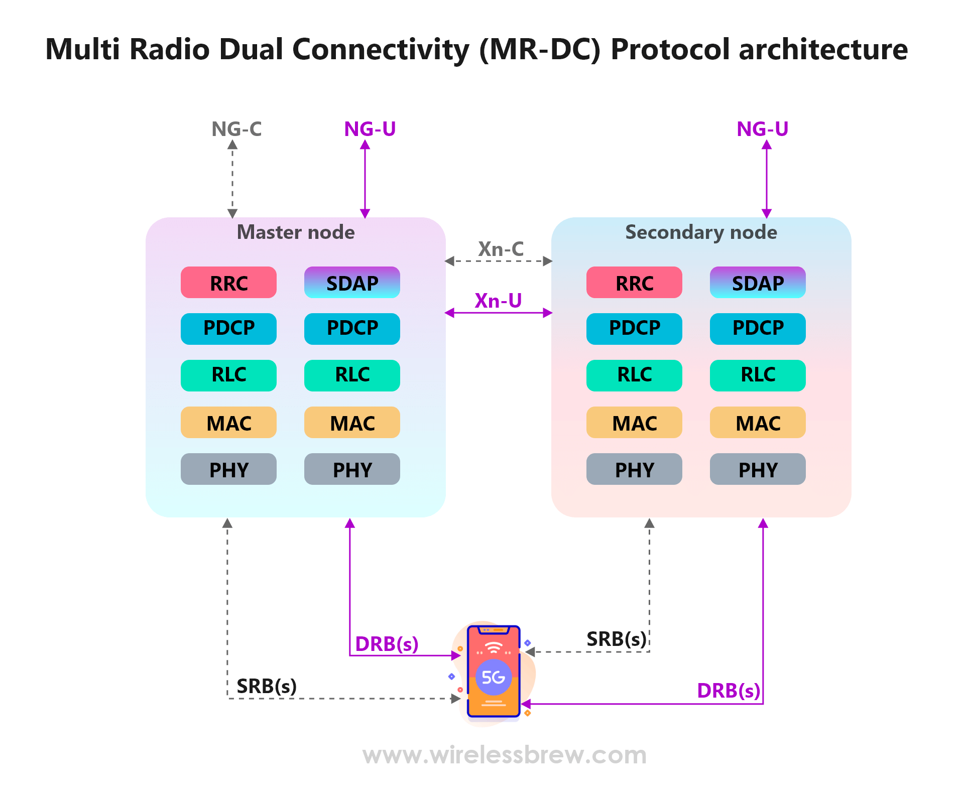
Multi Radio Dual Connectivity (MR-DC) Protocol Architecture
The network can ask the UE to report if it is NR-DC capable by setting the flag includeNR-DC in the IE UE-CapabilityRequestFilterCommon in UE Capability Inquiry.
UE-CapabilityRequestFilterCommon ::=  SEQUENCE {
    mrdc-Request  SEQUENCE {
        omitEN-DC                   ENUMERATED {true} OPTIONAL,  -- Need N
        includeNR-DC                ENUMERATED {true} OPTIONAL,  -- Need N
        includeNE-DC                ENUMERATED {true} OPTIONAL   -- Need N
    } OPTIONAL,                                              -- Need N
    ...
}
includeNR-DC: Only if this field is present, the UE supporting NR-DC shall indicate support for NR-DC in-band combinations and include feature set combinations that are applicable to NR-DC.
Signalling Radio Bearers in NR-DC
A UE in NR-DC mode can be configured with Data Radio Bearers (DRBs) and Signalling Radio Bearers (SRBs) on both MN and SN nodes.
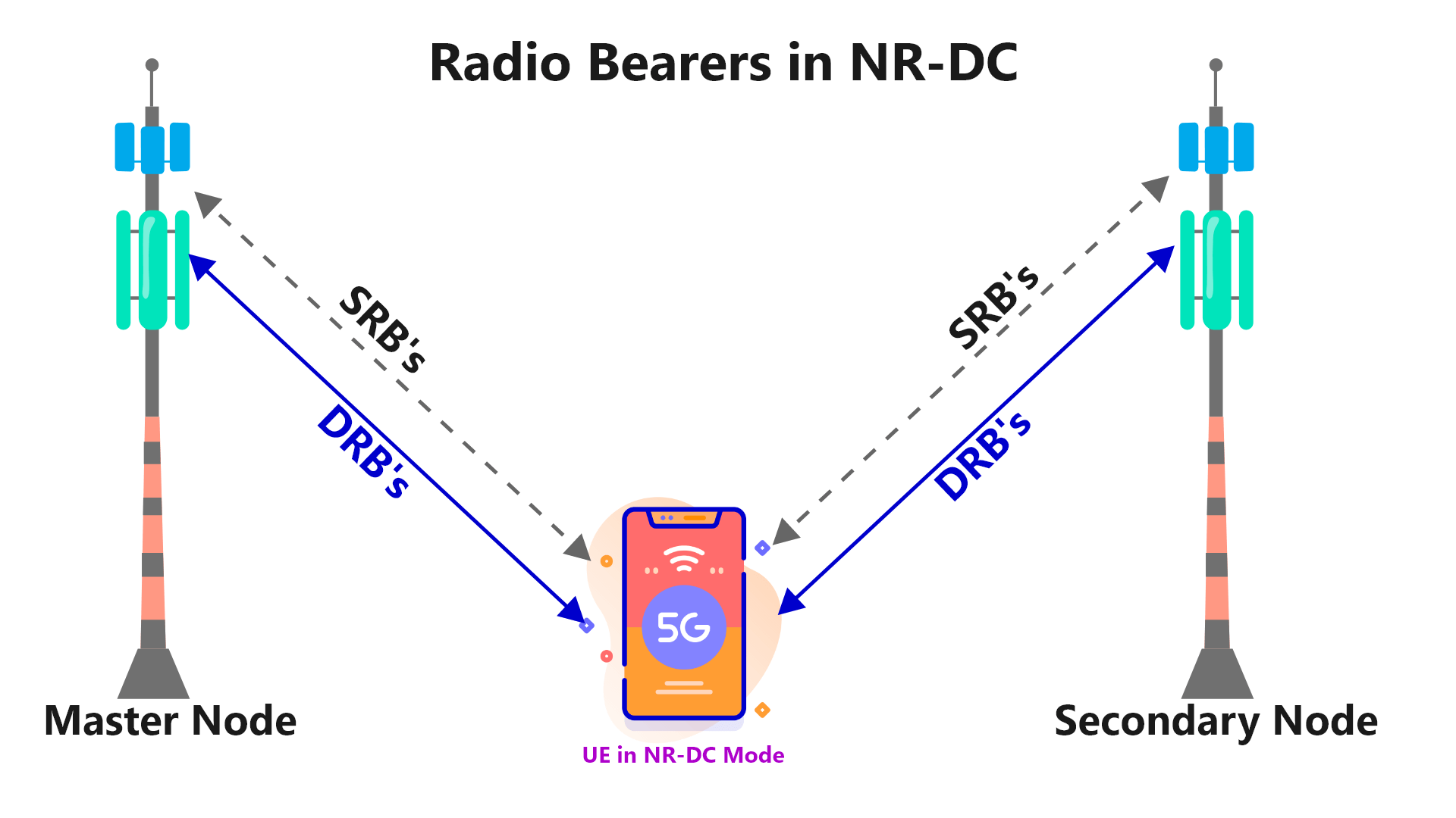
- Signaling between UE and Secondary Node: Done via SRB3 using the DCCH logical channel. SRB3 is also used when UE is in (NG)EN-DC mode.
- Split-SRB: The network can also configure Split-SRB where SRB can be used between the Master Node and Secondary Node.
- Configuration: When UE is configured with NR-DC,
mrdc-SecondaryCellGroupin the RRC Reconfiguration message is set tonr-SCG.
Radio Link Monitoring in NR-DC
When UE is in NR-DC Mode, UE can be configured to monitor Radio Link for both PCell and PSCell.
- The UE should be able to monitor the downlink radio link quality based on the reference signal configured as
RLM-RSresource(s) in order to detect the downlink radio link quality of the PCell and PSCell. - The network can configure all SSBs, or all CSI-RSs, or a mix of SSBs and CSI-RSs as
RLM-RSresources. - Constraint: UE is not expected to perform RLM outside the active DL BWP; it is expected to only perform inside the active DL BWP.
Measurements in NR-DC
The network can configure Measurement Configuration for both PCell and PSCell when UE is in NR-DC Connected mode.
When UE is in NR-DC, the UE may receive two independent measConfig from the network:
- A
measConfigassociated with MCG, included in theRRCReconfigurationmessage received via SRB1. - A
measConfigassociated with SCG, included in theRRCReconfigurationmessage received via SRB3, or embedded in anRRCReconfigurationmessage received via SRB1.
Reporting:
- With SRB3: If SRB3 is configured and a measurement report is triggered for the SCG, UE sends the
MeasurementReportmessage via SRB3. - Without SRB3: If SRB3 is not configured, UE sends
MeasurementReportmessage via SRB1 embedded in the NR RRC messageULInformationTransferMRDCof the PCell.
Failure Handling: A UE in NR-DC Mode configured with SRB3 detects MCG Failure, then it sends
MCGFailureInformationmessage embedded in NR RRC messageULInformationTransferMRDCvia SRB3 on the secondary node.
Key IEs for NR-DC
RRCReconfiguration IEs
mrdc-SecondaryCellGroup: Includes an RRC message for SCG configuration in NR-DC or NE-DC.- For NR-DC (
nr-SCG), this contains theRRCReconfigurationmessage generated entirely by the SN gNB. - Note: The RRC message can only include fields
secondaryCellGroup,otherConfig,conditionalReconfiguration, andmeasConfig.
- For NR-DC (
radioBearerConfig2: Configuration of Radio Bearers (DRBs, SRBs) including SDAP/PDCP. This IE can only be used if the UE supports NR-DC or NE-DC.secondaryCellGroup: Configuration of secondary cell group ((NG)EN-DC or NR-DC).
RRCResume IEs
mrdc-SecondaryCellGroup: Includes an RRC message for SCG configuration in NR-DC or NE-DC.radioBearerConfig2: Configuration of Radio Bearers (DRBs, SRBs) including SDAP/PDCP.
Summary
NR-NR Dual Connectivity (NR-DC) involves two gNBs acting as Master gNB and Secondary gNB.
- Rel-15 Scope: NR-DC in Rel-15 only includes the scenarios where all serving cells in MCG are in FR1 and all serving cells in SCG are in FR2.
WirelessBrew Team
Technical expert at WirelessBrew, specializing in 5G NR, LTE, and wireless system optimization. Committed to providing accurate, 3GPP-compliant engineering tools.
Up Next
More 5g nr Articles →